Hardware Platforms
Warning
This project is under development and not ready for use.
Supported Sensor Boards
This library supports almost all XENSIV™ PAS Gas Sensors family. This includes the mini boards, wing boards as well as the Shield2Go boards of the sensors. Following you will see a list of boards which are supported by this library.
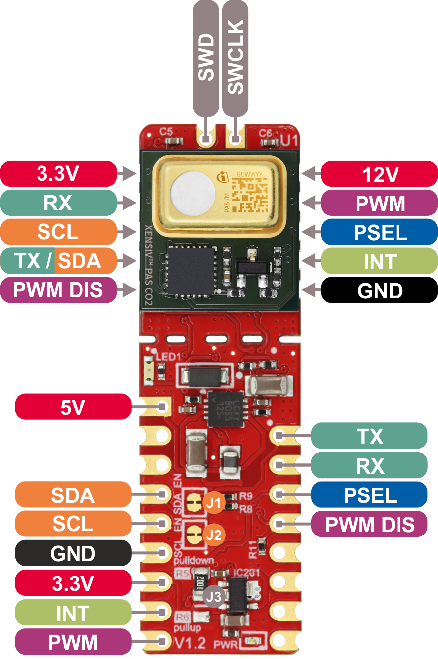
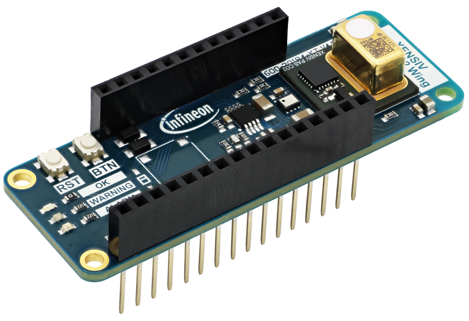
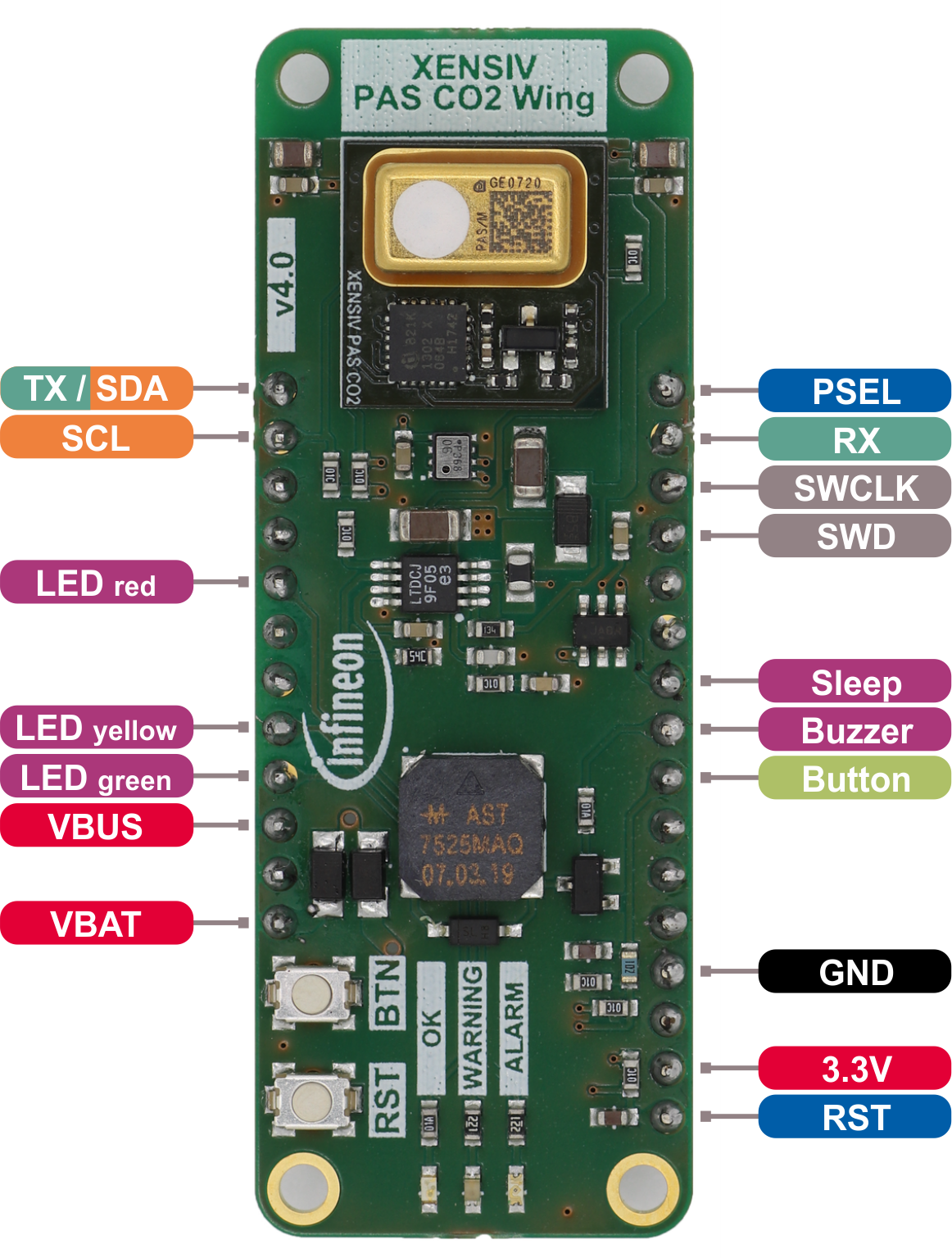
XENSIV™ PAS CO2 Sensor Shield2Go
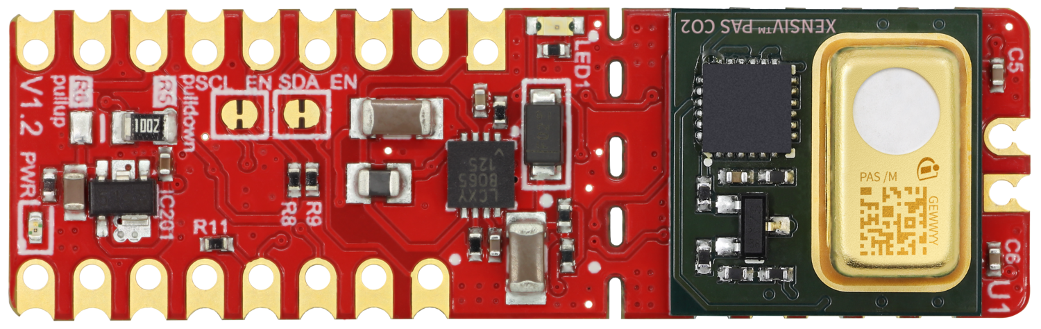
Pinout Diagram
Warning
All signal pins run on 3.3V logic!
Pin Description
Pin Name |
Description |
|---|---|
5V |
5V supply input. |
SDA |
I2C SDA (serial data). |
SCL |
I2C SCL (serial clock). |
GND |
Supply and signal ground. |
3.3V |
3.3V supply input - use as logic supply when using breakable part stand-alone, else keep NC. |
INT |
Interrupt output. |
PWM |
PWM signal output. |
TX |
UART transmit side. |
RX |
UART receive side. |
PSEL |
Communication interface selection. |
PWM DIS |
PWM disable input (set high to disable PWM). |
5V |
5V supply input - use as sensor supply when using breakable part stand-alone, else keep NC. |
TX/SDA |
UART transmit or I2C SDA (serial data), depending on selected communication interface. |
SWD |
Serial wire debug data (keep NC). |
SWCLK |
Serial wire debug clock (keep NC). |
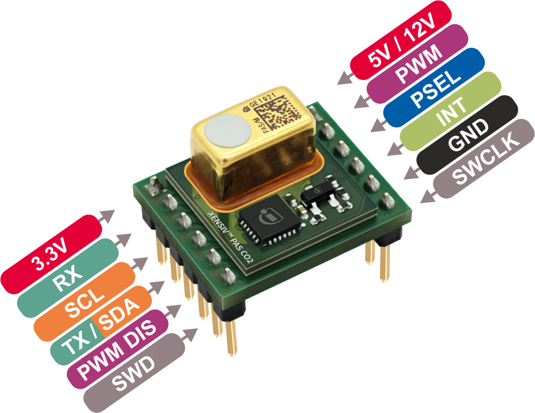
XENSIV™ PAS CO2 Miniboard
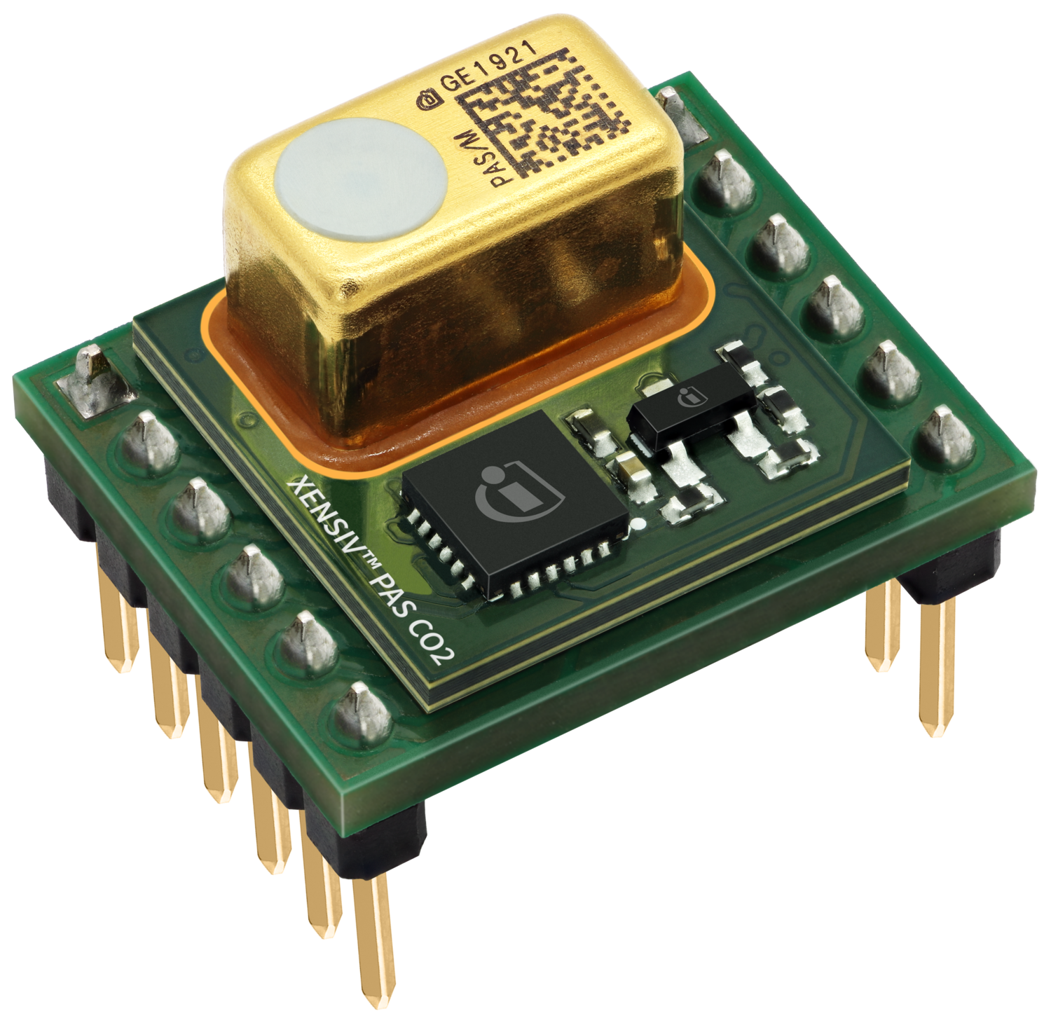
Pinout Diagram
Warning
Caution! Verify your sensor version before you connect the 5V / 12V input. The 5V version of the sensor does not tolerate 12V!
Pin Description
Pin Name |
Description |
|---|---|
SDA |
I2C SDA (serial data). |
SCL |
I2C SCL (serial clock). |
GND |
Supply and signal ground. |
3.3V |
3.3V logic supply input (required). |
INT |
Interrupt output. |
PWM |
PWM signal output. |
RX |
UART receive side. |
PSEL |
Communication interface selection. |
PWM DIS |
PWM disable input (set high to disable PWM). |
5V/12V |
5V/12V sensor supply input (required). |
TX/SDA |
UART transmit or I2C SDA (serial data), depending on selected communication interface. |
SWD |
Serial wire debug data (keep NC). |
SWCLK |
Serial wire debug clock (keep NC). |
KIT_CSK_PASCO2
Pinout Diagram
Warning
Caution! Verify your sensor version before you connect the 5V / 12V input. The 5V version of the sensor does not tolerate 12V!
XENSIV™ PAS R290 Miniboard

Pinout Diagram

Pin Description
Pin Name |
Description |
|---|---|
SDA |
I2C SDA (serial data). |
SCL |
I2C SCL (serial clock). |
GND |
Supply and signal ground. |
3.3V |
3.3V logic supply input (required). |
INT |
Interrupt output. |
PWM |
PWM signal output. |
RX |
UART receive side. |
PSEL |
Communication interface selection. |
PWM DIS |
PWM disable input (set high to disable PWM). |
5V |
5V sensor supply input (required). |
TX/SDA |
UART transmit or I2C SDA (serial data), depending on selected communication interface. |
SWD |
Serial wire debug data (keep NC). |
SWCLK |
Serial wire debug clock (keep NC). |
XENSIV™ PAS A2L Miniboard

Pinout Diagram

Pin Description
Pin Name |
Description |
|---|---|
SDA |
I2C SDA (serial data). |
SCL |
I2C SCL (serial clock). |
GND |
Supply and signal ground. |
3.3V |
3.3V logic supply input (required). |
INT |
Interrupt output. |
PWM |
PWM signal output. |
RX |
UART receive side. |
PSEL |
Communication interface selection. |
PWM DIS |
PWM disable input (set high to disable PWM). |
5V |
5V sensor supply input (required). |
TX/SDA |
UART transmit or I2C SDA (serial data), depending on selected communication interface. |
SWD |
Serial wire debug data (keep NC). |
SWCLK |
Serial wire debug clock (keep NC). |
Supported MCU Platforms
Find out which boards are build checked under continuous integration here.